Precision Time Protocol (PTP, IEEE 1588) keeps clocks within a microsecond or better by timestamping packets in hardware and letting switches correct for their own delay. NTP runs the same four-timestamp maths in software and usually holds a LAN to around a millisecond. Pick NTP for logs, Kerberos and everyday IT. Pick PTP when your budget is measured in microseconds.
That’s the short version. The longer one is more interesting, because the arithmetic inside both protocols is the same. What changes is where each clock reads the time, and whether the network owns up to its own delay.
PTP vs NTP: what’s the difference at a glance?
| NTP | PTP | |
|---|---|---|
| Standard | RFC 5905 (NTPv4) | IEEE 1588-2019 (PTP v2.1) |
| Typical accuracy | A few hundred µs to about 1 ms on a LAN, tens of ms over the internet | Sub-microsecond with hardware timestamps and PTP-aware switches |
| Where the timestamp is taken | Usually in software, after the packet has climbed the OS stack | In the NIC or switch hardware, as the packet crosses the wire |
| What the switches do | Forward it like any other packet. Their delay is noise | Boundary and transparent clocks measure and remove their own delay |
| Hierarchy | Stratum 1 to 15. Stratum 16 means unsynchronised | One grandmaster, elected by the best master clock algorithm |
| Message rate | Cisco: about one packet a minute holds 1 ms | One Sync per second by default, up to 8 per second on a Catalyst 9300 |
| Transport | UDP 123 | UDP 319 and 320, or raw Ethernet (EtherType 0x88F7) |
| What you need to buy | Nothing new | PTP-aware NICs and switches, plus a grandmaster |
| Typical jobs | Logs, authentication, servers, network gear | 5G radio, trading, power substations, broadcast audio and video |
The NTP figures come straight from RFC 5905, which says typical clients on fast LANs sit “within a few hundred microseconds”, and from Cisco’s own NTP guide, which says one packet a minute keeps two devices “within a millisecond of one another”. The PTP figure matches a widely cited 2015 IEEE paper on PTP in substations (Watt et al., Understanding and Applying Precision Time Protocol), which calls it a way of “achieving submicrosecond synchronization accuracy” over Ethernet.
What is precision time protocol?
Precision time protocol is a packet-based way to share one clock across a network so precisely that every device agrees on the time to within nanoseconds or a few hundred nanoseconds. It’s defined in IEEE 1588, the Standard for a Precision Clock Synchronization Protocol for Networked Measurement and Control Systems. That’s why you’ll see “IEEE 1588”, “PTP protocol” and “precision time protocol” used as the same thing.
There have been three editions:
- 1588-2002 – PTP version 1.
- 1588-2008 – PTP version 2. Still what most gear means by “PTPv2”, and what a Cisco
show ptp portprints asPTP version: 2. - 1588-2019 – version 2.1, the current edition.
Since 2019 the IEEE has added several amendments (2022 to 2024) and, as of mid-2026, is working on a roll-up revision that folds them in. It isn’t published yet. One amendment worth knowing is 1588g-2022. It adds optional alternative terms, timeTransmitter and timeReceiver, for master and slave. It doesn’t remove the old ones, which is why Cisco’s CLI still prints MASTER and SLAVE while newer commands say ptp role primary.
Honestly, this matters more than it sounds. Exam questions and show output use the old words. Standards drafts and new vendor docs use the new ones. You’ll need both.
What is PTP time?
PTP doesn’t count in UTC. Its default timescale is TAI, International Atomic Time, which never adds leap seconds. Announce messages carry the current UTC offset so each device can convert. Right now TAI is 37 seconds ahead of UTC, and the IERS confirmed in its July 2026 Bulletin C that no leap second will be added at the end of December 2026. So that 37 holds into 2027.
How does PTP protocol work?
A master clock and a slave clock swap four messages and record four timestamps. Here’s the delay request-response exchange, as Cisco’s Catalyst 9300 guide lays it out:
- The master sends a Sync message and notes when it left: t1.
- The slave notes when the Sync arrived: t2.
- The master sends t1 inside a Follow_Up message.
- The slave sends a Delay_Req and notes when it left: t3.
- The master notes when the Delay_Req arrived: t4.
- The master sends t4 back inside a Delay_Resp.
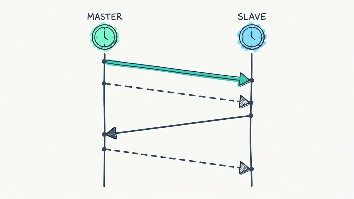
The four messages in order. Sync (the turquoise arrow) is sent at t1 and received at t2. The dashed Follow_Up carries t1. Delay_Req goes back, sent at t3 and received at t4. The last dashed arrow, Delay_Resp, carries t4.
Now the slave has all four numbers, and it works out two things:
meanPathDelay = ((t2 - t1) + (t4 - t3)) / 2
offset        = (t2 - t1) - meanPathDelay
Say t1 = 1,000,000 ns, t2 = 1,005,470, t3 = 1,055,470 and t4 = 1,056,940. The trip there looks like 5,470 ns and the trip back looks like 1,470 ns. Average them and the one-way delay is 3,470 ns. Take that off the trip there and you get the offset: the slave is 2,000 ns ahead, so it winds itself back by 2 µs. Simple, right?
There’s one assumption hiding in that maths. The path has to take the same time in both directions. Hold that thought.
Which PTP messages carry timestamps?
PTP splits its messages into two groups, and plenty of explainers get this wrong:
- Event messages are timestamped in hardware as they cross the port: Sync, Delay_Req, Pdelay_Req, Pdelay_Resp.
- General messages aren’t: Announce, Follow_Up, Delay_Resp, Pdelay_Resp_Follow_Up, plus Signaling and Management.
Follow_Up and Delay_Resp only carry timestamps taken earlier. They don’t need one of their own.
What’s the difference between one-step and two-step?
In two-step mode, the master sends Sync, then sends the exact departure time in a Follow_Up. In one-step mode, the hardware writes t1 into the Sync as it leaves, so there’s no Follow_Up. One-step needs smarter hardware but halves the Sync traffic.
Check your platform. Cisco’s Catalyst 9300 guide says its PTP supports two-step only, and it drops one-step messages from a grandmaster. The G.8275.1 telecom profile on the same switch accepts both.
Why is PTP more accurate than NTP?
Here’s the surprise. NTP uses the same arithmetic. RFC 5905 computes the offset as half of (T2 – T1) plus (T3 – T4). That’s the PTP formula with the roles flipped, because in NTP the client speaks first. So the accuracy gap isn’t about cleverer maths. It comes from three places.
1. Where the timestamp is taken. A PTP-capable NIC or switch stamps the packet at the wire. A typical NTP client takes its timestamp in software, after an interrupt, a driver and the kernel have had their turn. Every microsecond of that path that varies goes straight into the result. On Linux you can see which kind you have: ethtool -T <interface> lists hardware-transmit and hardware-receive only if the NIC and driver can do it, plus the index of the PTP hardware clock.
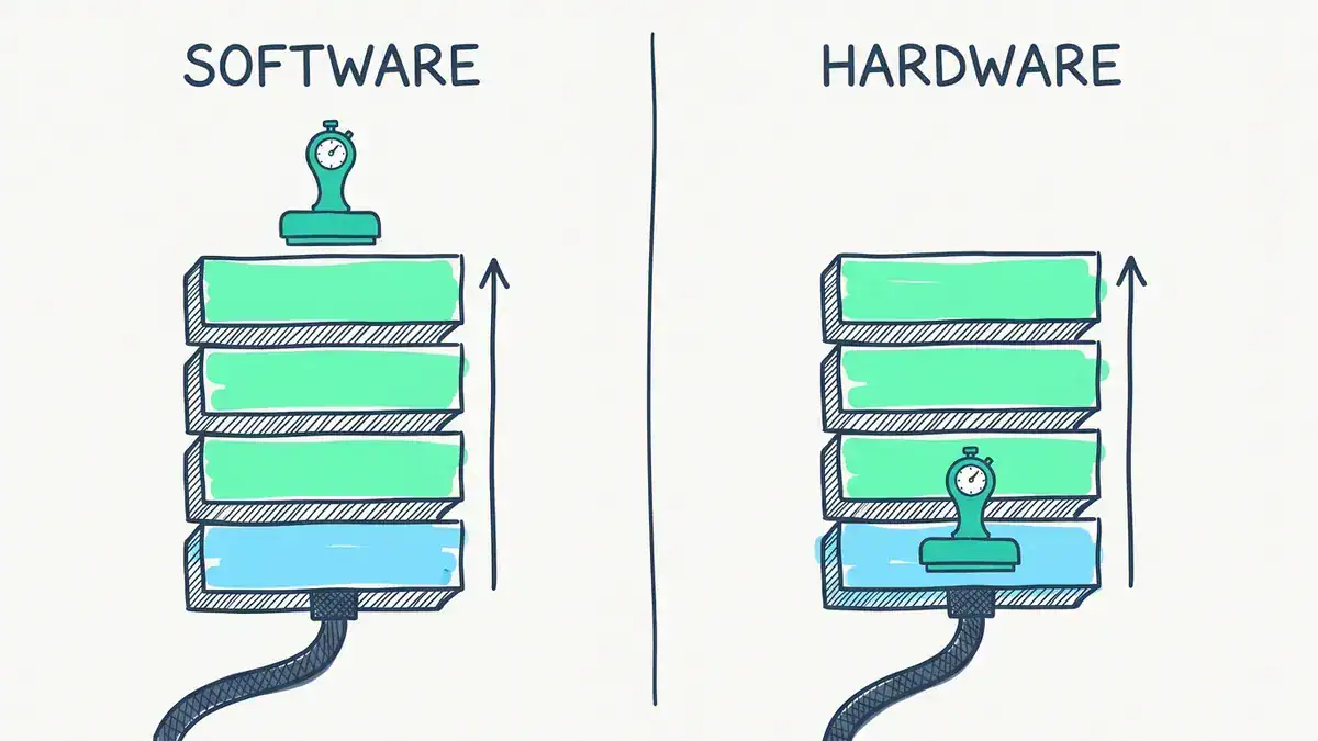
Where the timestamp is taken. In software it’s written after the packet has climbed through the network card, driver, kernel and application. In hardware it’s written at the wire, before any of those can add delay.
2. Whether the network helps. To NTP, a switch is a black box. If a packet sits in a queue, NTP sees a noisy sample and tries to filter it out. RFC 5905’s clock filter keeps the last eight samples and favours the ones most likely to be clean. PTP goes further. Boundary clocks and transparent clocks measure their own delay and either remove it or write it into the packet, so the noise never reaches the slave.
3. How often it measures. Cisco says NTP needs “no more than one packet per minute” to hold a millisecond. PTP’s default on a Catalyst 9300 is one Sync per second, and ptp sync interval -3 raises that to eight. That’s 60 or 480 measurements in the minute NTP takes for one.
How accurate is NTP, really?
Better than most comparison tables admit. RFC 5905 puts typical primary servers “within a few tens of microseconds” and LAN clients “within a few hundred microseconds”. Over the internet with long poll intervals, it’s “a few tens of milliseconds”.
Microsoft is even more specific. Windows 10, Windows Server 2016 and later can hold 1 ms to a reference, but only if you meet all of this: under 0.1 ms of network latency to the time source, four hops or fewer, stratum 5 or better, and average CPU under 80%, on the host too if it’s a VM. That’s from Microsoft’s support boundary for high-accuracy time, updated 2026-02-12. Read it as “1 ms is NTP working hard”.
So the honest line is this. NTP isn’t stuck at 10 ms. It’s stuck at whatever your software stack and your switches add, and it can’t see either.
Worked example: what does one queued frame do to your clock?
Let’s put numbers on that “same delay both ways” assumption. The topology is a grandmaster, two switches and a slave, joined by three 100 m fibre links. The slave really is 2,000 ns ahead. Light in fibre takes about 4.9 ns per metre, and each idle switch adds 1,000 ns each way.
Then one thing goes wrong. In switch A, the Sync lands behind a single full-size frame heading out of the same 1 Gb/s port. On the wire that frame is 1,538 bytes: the 1,518-byte Ethernet frame plus 8 bytes of preamble and start delimiter and a 12-byte inter-frame gap. At 1 Gb/s it takes 12,304 ns to clear the port. The Delay_Req coming back doesn’t hit a queue.
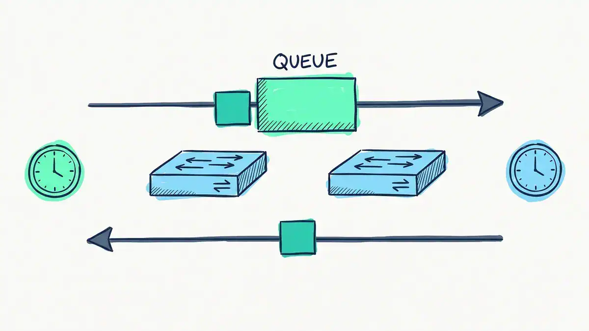
Case 1 in the table below. One 1,538-byte frame (12,304 ns at 1 Gb/s) sits ahead of the Sync in switch A, so only the master-to-slave path is slowed. The return path is clear.
Here’s what the slave calculates in five versions of that network. All times are in nanoseconds:
| Case | Master to slave | Slave to master | meanPathDelay | Offset the slave computes | Error |
|---|---|---|---|---|---|
| 0. Idle network, ordinary switches | 3,470 | 3,470 | 3,470 | 2,000 | 0 |
| 1. Sync queued once, ordinary switches | 15,774 | 3,470 | 9,622 | 8,152 | +6,152 |
| 2. Same queue, both switches are E2E transparent clocks | 15,774 | 3,470 | 1,470 | 2,000 | 0 |
| 3. Transparent clocks, but the return fibre on the last link is 20 m longer | 15,774 | 3,568 | 1,519 | 1,951 | -49 |
| 4. Same queue hits both directions, ordinary switches | 15,774 | 15,774 | 15,774 | 2,000 | 0 |
These come from a short Python model of the protocol arithmetic that we wrote for this post and checked line by line. They’re not a capture from a live switch. Four things fall out of it.
One frame costs you 6 µs. The error is exactly half the asymmetry: 12,304 / 2 = 6,152 ns. A 5G TDD radio has a budget of about ±1.5 µs end to end, so that’s four times over from one frame on one port. An NTP client in the same spot gets the same error, plus whatever its software adds.
Delay isn’t the enemy. Asymmetry is. Case 4 has more delay than case 1, and the error is zero, because the queue hit both directions equally and cancelled out. Your network can be slow. It can’t be lopsided.
Transparent clocks remove queueing. In case 2 each switch writes its residence time into the message’s correctionField and the slave subtracts it. The 12 µs disappears. Notice that meanPathDelay drops to 1,470 ns too. That’s just the fibre.
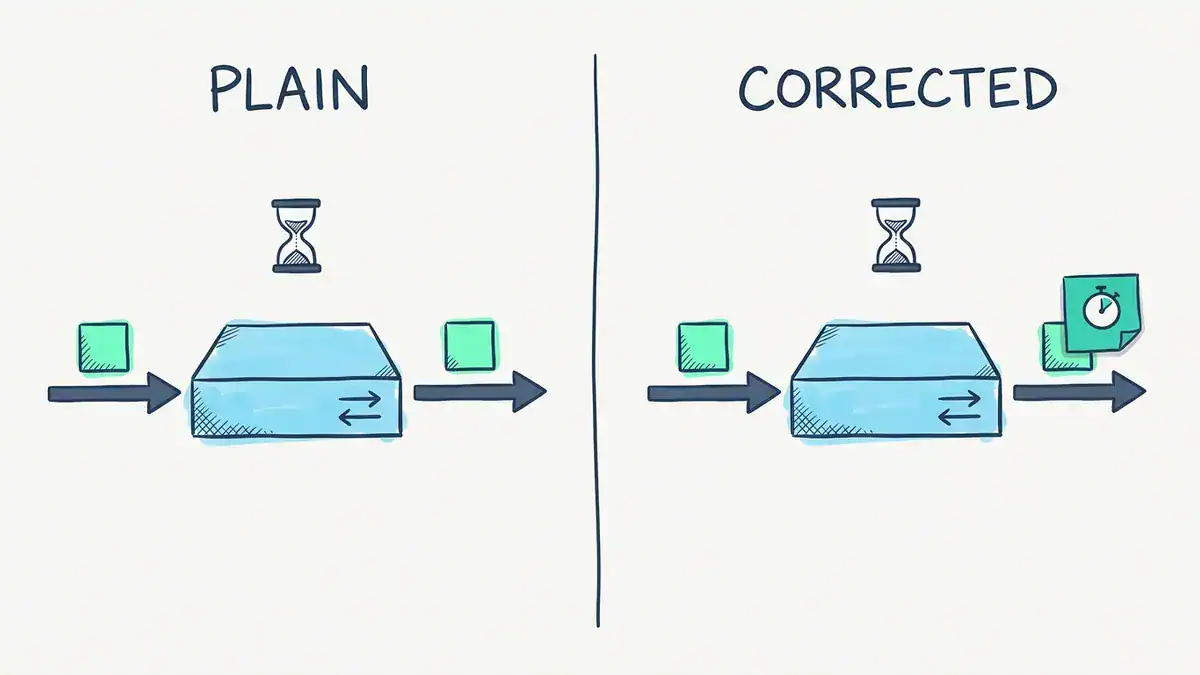
What a transparent clock adds. In case 2, switch A writes 13,304 ns (1,000 idle plus 12,304 queued) and switch B writes 1,000 ns into the correctionField. The slave subtracts the 14,304 ns total.
Nothing in the protocol fixes cable asymmetry. In case 3, 20 extra metres of fibre on the return path leave a 49 ns error that no transparent clock can see, because it’s in the glass, not the switch. At nanosecond budgets you measure and compensate for that per link.
What are the PTP clock types?
Every PTP device is one of four clock types. Get these straight and most config makes sense.
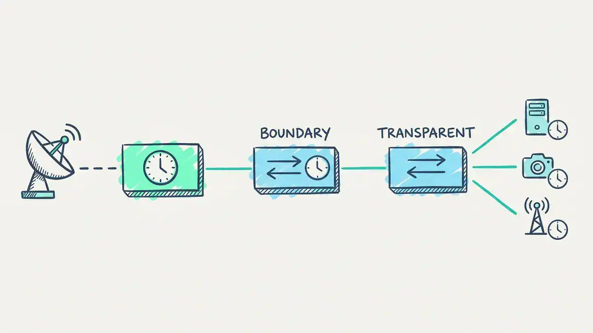
One timing hierarchy. The dish is the GNSS source and the grandmaster is the root. The boundary clock re-times its own ports. The transparent clock only corrects the packets passing through. The server, camera and radio mast are ordinary clocks.
What is a PTP grandmaster clock?
The grandmaster is the root of time for a PTP domain. Cisco describes it as usually having “a very precise time source, such as a GPS or atomic clock”. It can also free-run when the network only needs to agree internally, not match UTC. A dedicated grandmaster appliance with a GNSS receiver is the usual choice for a PTP time server.
What is a PTP ordinary clock?
An ordinary clock has one PTP port. It’s either a master or, far more often, a slave: the server, radio unit, camera or protection relay at the edge that actually needs the time.
What is a PTP boundary clock?
A boundary clock has several PTP ports. One port syncs to the master upstream as a slave. Every other port acts as a master for the devices below. It terminates PTP, so each segment is its own short, clean exchange. Cisco recommends boundary mode “when overload or heavy load conditions produce significant delay jitter”.
What is a PTP transparent clock?
A transparent clock doesn’t sync to anything. It measures how long each event message spent inside it, its residence time, and adds that to the message’s correctionField. There are two kinds:
- End-to-end (E2E) transparent clocks correct for residence time only.
- Peer-to-peer (P2P) transparent clocks also measure the link delay to the neighbour, using Pdelay messages, and add that too.
PTP boundary clock vs transparent clock: which should you use?
| Boundary clock | Transparent clock | |
|---|---|---|
| Syncs its own clock | Yes | No (E2E). P2P only measures links |
| Splits the domain | Yes, each hop is a new master-slave pair | No, the slave still talks to the grandmaster |
| What it fixes | Everything upstream, by re-timing | Its own residence time (and link delay, if P2P) |
| Scales to large networks | Better, the grandmaster sees few slaves | All slaves load the grandmaster |
| Cisco 9300 note | Supported on native Layer 3 ports | Not on native Layer 3 ports or EtherChannel |
Cisco’s guide says its e2etransparent mode “causes less jitter and error accumulation than boundary mode”, and that boundary mode suits heavy, jittery load. So there’s no universal winner. Check what your profile allows (G.8275.1 on a 9300 permits E2E transparent clocks only, never P2P), then pick per hop. Either one beats a switch that does neither.
How does the best master clock algorithm pick a grandmaster?
Every clock runs the best master clock algorithm (BMCA) on what it hears in Announce messages, and the lowest value wins at each step:
- Priority1 – set by you, 0 to 255, default 128.
- clockClass – what the clock is locked to.
- Accuracy – how close it claims to be to UTC.
- Variance – how stable it is.
- Priority2 – your tie-breaker, 0 to 255, default 128.
- Clock identity – a unique 64-bit ID, the final tie-breaker.
Sound familiar? It’s the same idea as the root bridge election in spanning tree: priority first, then an ID. But it’s a separate tree. Cisco notes that from IOS XE 17.6.4 the default PTP profile builds its own sync tree, which can differ from spanning tree. Also, a clock with priority1 255 can never become grandmaster, which is a handy way to keep a switch out of the election.
What is PTP clock class?
clockClass tells everyone how trustworthy a clock is right now. The values you’ll actually see:
| clockClass | Meaning |
|---|---|
| 6 | Locked to a primary reference time source, such as GNSS. Can’t be a slave |
| 7 | Was class 6, lost its reference, now in holdover and still within spec |
| 52 | Class 7 that has drifted outside holdover spec (alternative A). Can’t be a slave |
| 187 | Same as 52 (alternative B), but it may become a slave |
| 248 | Default. Used when nothing else applies |
| 255 | Slave-only clock |
Source: the clockClass table in Cisco’s PTP primer. You’ll see 6 on a healthy grandmaster and 248 on a switch that’s just doing its job.
Which PTP profile do you need?
A profile is a set of PTP choices for one industry: which delay mechanism, which message rates, which transport, which clock types are allowed. Pick the one your devices speak:
- Default profile – the general-purpose one in IEEE 1588 itself. Layer 2 or UDP/IPv4.
- ITU-T G.8275.1 (telecom) – for mobile networks with PTP support at every hop. On the Catalyst 9300 it allows only E2E transparent clocks and uses Sync, Follow_Up, Announce, Delay_Req and Delay_Resp.
- ITU-T G.8275.2 – the telecom profile for networks where not every hop supports PTP.
- AES67 (media) – audio over IP. It marks PTP with DSCP 46, expedited forwarding, so timing packets jump the queue.
- SMPTE ST 2059-2 – broadcast video. Not a native profile on the 9300, though Cisco notes it can work if it runs with AES67 settings.
- IEEE C37.238 – the power profile for substations.
- IEEE 802.1AS (gPTP) – for audio video bridging and time-sensitive networking.
What is gPTP?
gPTP, generalized precision time protocol, is the IEEE 802.1AS profile of PTP used for audio video bridging (AVB) and time-sensitive networking (TSN). Every bridge is time-aware and acts as a boundary clock that measures link delay with the peer-to-peer mechanism. Per Cisco, gPTP uses domain 0 only, and on a Catalyst 9300 it’s mutually exclusive with the default 1588 profile, so one or the other runs at a time. Some 9300 models also can’t run gPTP at 100 Mb/s.
What’s in a PTP packet?
PTP runs over two transports. Both are simple once you know the numbers:
| Transport | How PTP travels |
|---|---|
| Layer 2 Ethernet | EtherType 0x88F7. Multicast MAC 01-1B-19-00-00-00 for most messages, 01-80-C2-00-00-0E for peer delay |
| UDP over IPv4 | UDP 319 for event messages, UDP 320 for general messages. Multicast 224.0.1.129, or 224.0.0.107 for peer delay |
Compare that with NTP, which only ever uses UDP 123. If you’re learning ports for an exam, our common ports cheat sheet covers 123 alongside the rest.
Every PTP message shares one common header. The fields that matter day to day are the message type, the version, the domain number (so several PTP systems can share one network), the correctionField where transparent clocks add residence time, the source port identity and a sequence ID that ties each Follow_Up to its Sync.
What is PTP hardware timestamping?
PTP hardware timestamping means the NIC or switch ASIC records the exact moment a PTP packet crosses the port, using its own PTP hardware clock, before the operating system ever sees it. That’s what removes software jitter from t1 to t4.
It isn’t only for on-site gear anymore. AWS added a PTP hardware clock to EC2 instances on the Nitro System. In its 2023 announcement, AWS says you’ll typically see a clock error bound under 100 µs over its NTP service and under 40 µs through the PTP hardware clock, on the same instance and the same time source. That’s the NTP vs PTP gap in one line. The EC2 precision clock guide adds that the same clock can stamp every incoming packet with a 64-bit nanosecond timestamp, on Linux instances that meet its requirements.
SyncE vs PTP: frequency or time?
SyncE (Synchronous Ethernet) carries frequency. PTP carries time and phase. SyncE recovers a clock from the Ethernet physical signal itself, so every hop’s oscillator ticks at the same rate. It’s very stable, but it can’t tell anyone what time it is. PTP does that over packets.
They aren’t rivals. Mobile networks commonly run both: SyncE keeps every node’s frequency rock steady, and PTP rides on top to align phase and time of day. If you only need devices to tick at the same rate, SyncE alone can do it. If you need them to agree on when, you need PTP.
NTP vs PTP vs GPS: which one is the time source?
GPS isn’t a third option next to NTP and PTP. It’s the source. A GNSS receiver gives a grandmaster (or an NTP stratum 1 server) its time. NTP and PTP then carry that time across the network.
Could you just put a GPS receiver on every device? You’d need an antenna with a view of the sky for each one, which rarely works in a data centre or a substation. PTP lets one well-placed grandmaster serve the lot. And PTP doesn’t strictly need GPS at all: Cisco notes a grandmaster can free-run when devices only need to agree with each other.
How do you configure precision time protocol on Cisco?
Here’s a boundary clock on a Catalyst 9300, built from Cisco’s IOS XE 17.18 PTP configuration guide. PTP is disabled globally by default on these switches. The ptp mode command is the step that switches it on.
! Boundary clock using delay request-response (E2E)
Switch(config)# ptp mode boundary delay-req
! Keep this switch from ever winning the grandmaster election
Switch(config)# ptp priority1 255
!
! Uplink trunk towards the grandmaster
Switch(config)# interface TenGigabitEthernet1/0/1
Switch(config-if)# ptp vlan 5
Switch(config-if)# ptp sync interval -3
Switch(config-if)# exit
!
! Access port to an end device: this port stays master,
! so the device below can't take over as grandmaster
Switch(config)# interface GigabitEthernet1/0/10
Switch(config-if)# ptp role primary
Switch(config-if)# exit
!
! A port that shouldn't run PTP at all
Switch(config)# interface GigabitEthernet1/0/48
Switch(config-if)# no ptp enable
A few things worth knowing about those lines:
- Once the default profile is on, PTP runs on every interface. You switch it off per port with
no ptp enable. ptp vlanpicks the VLAN for PTP on a trunk. The default is the native VLAN, and in boundary mode PTP packets on other VLANs are dropped. The PTP VLAN must exist and be allowed on the trunk. (New to trunks? See what a VLAN is and how tagging works.)- Timers are log base 2.
ptp sync interval -3means 2^-3 seconds, so 8 Syncs a second. The range is -3 to 1 and the default is 0, one per second.ptp announce intervaldefaults to 0 as well, with a timeout of 3 intervals. - For transparent mode, use
ptp mode e2etransparentorptp mode p2ptransparentinstead.
How do you verify PTP on a Cisco switch?
Three commands do most of the work. This is Cisco’s sample output from the same guide, trimmed. It comes from a switch left at the default priorities, so it shows 128, not the 255 we set above:
Switch# show ptp brief
Interface                       Domain    PTP State
TenGigabitEthernet1/0/1         0         MASTER
TenGigabitEthernet1/0/2         0         SLAVE
TenGigabitEthernet1/0/3         0         FAULTY

Switch# show ptp clock
PTP CLOCK INFO
PTP Device Type: Boundary clock
PTP Device Profile: Default Profile
Clock Domain: 0
Priority1: 128
Priority2: 128
Clock Quality:
Class: 248
Offset From Master(ns): 0
Mean Path Delay(ns): 0

Switch# show ptp parent
Grandmaster Clock:
Grandmaster Clock Identity: 0x0:11:1:FF:FE:0:0:1
Grandmaster Clock Quality:
Class: 6
Accuracy: Within 25ns
Priority1: 128
Priority2: 128
Read it like this. show ptp brief gives each port’s state: one SLAVE towards the grandmaster, MASTER towards everything below. show ptp clock describes this switch: a boundary clock at class 248, the default. show ptp parent describes the grandmaster it follows: class 6, so it’s locked to a primary reference, and it claims accuracy within 25 ns. On a live network, the two numbers to watch are Offset From Master and Mean Path Delay.
What are the Cisco PTP gotchas?
These come from the restrictions in Cisco’s 9300 guide, and they’re the ones that bite:
- Two-step only. One-step Syncs from a grandmaster are dropped.
- Multicast only, IPv4 only. IPv6 and VRFs don’t support PTP.
- EtherChannel: configure PTP on the member links, not the port-channel. The lowest-numbered member becomes the slave port and the rest go passive. More on bundles in our EtherChannel and LACP guide.
- Stacks: Cisco warns that stacking all eight members may reduce performance or skew delay and offset values. If you’re choosing a design, see switch stacking vs VSS vs vPC.
- SD-Access fabric switches don’t hardware-timestamp PTP in the overlay, so accuracy drops with every hop. Our SD-Access virtual lab PDF shows the fabric pieces involved.
- PTP and the system clock are separate. Cisco says syncing the PTP clock from the system clock, or the other way round, isn’t supported. The switch’s own logs still need NTP.
What does NTP look like on the same switch?
For contrast, here’s the NTP side. It’s short:
Switch(config)# ntp server 192.0.2.10 prefer
Switch(config)# ntp server 192.0.2.11
Switch# show ntp associations
Switch# show ntp status
show ntp associations lists each server, its stratum and its offset, with * marking the one you’re synced to. Cisco’s NTP verification guide walks through every column. Two Cisco details catch people out. Catalyst switches can’t act as stratum 1, because you can’t attach a radio or atomic clock. And ntp master makes a switch an authoritative source even when it isn’t synced to anything, which Cisco warns can override good time sources. Use it with care.
If you want to see NTP working on a real topology, the network services labs in our CCNA lab workbook build it alongside DHCP, DNS and SNMP.
When should you use PTP instead of NTP?
The PTP vs NTP decision starts from your accuracy budget, not from the protocol. Here’s what real requirements look like:
| Requirement | Budget | Where it comes from | Use |
|---|---|---|---|
| Kerberos authentication | 5 minutes | Microsoft’s default maximum clock tolerance | NTP |
| Log and SIEM correlation | Milliseconds | Your own investigation needs | NTP |
| High-accuracy Windows time | 1 ms | Microsoft’s support boundary, with strict conditions | NTP, done carefully |
| High-frequency trading in the EU | 100 µs from UTC, 1 µs granularity | MiFID II, RTS 25 | PTP with hardware timestamps |
| Microsecond time in the cloud | Under 40 µs | AWS EC2 PTP hardware clock | PTP hardware clock |
| 5G and LTE TDD radio | About ±1.5 µs end to end | ITU-T G.8271 | PTP telecom profile, often with SyncE |
| Substations, broadcast, industrial control | Microseconds or better | IEEE C37.238, SMPTE ST 2059, AES67 | PTP with the matching profile |
A rule of thumb, not a standard. If your budget is 1 ms or more, NTP will do it. Somewhere between 1 ms and about 10 µs, it depends on how clean your network and hosts are. Below that, you need PTP with hardware timestamps at both ends and PTP-aware switches in between.
And most sites run both. PTP feeds the handful of systems that need it. NTP looks after everything else, including the switches themselves.
How do you roll out precision time protocol?
- Write down the budget. A number in µs, end to end, at the device that needs it.
- Buy a grandmaster with a GNSS input and good holdover, so a lost antenna drops you to class 7, not straight to class 248.
- Make every hop PTP-aware with boundary or transparent clocks. One ordinary switch in the path reintroduces the errors in our worked example.
- Check hardware timestamping at the edges. On Linux,
ethtool -T. - Pick one profile and one domain that every device supports.
- Prioritise PTP traffic. DSCP 46 is the usual marking.
- Measure. Watch offset from master over days, not minutes, and look for asymmetric links.
What does the ENCOR exam test on NTP and PTP?
The ENCOR 350-401 v1.2 blueprint puts it under 3.0 Infrastructure, 30% of the exam, objective 3.3.a: “Interpret network time protocol configurations such as NTP and PTP.” That’s from Cisco’s ENCOR v1.2 exam topics, read 2026-10-25.
Notice the verb. Interpret. You’re expected to read a config or show output and say what it does, not design a timing network. In practice that means you should be able to:
- Tell boundary mode from transparent mode in a config.
- Read
show ptp clockandshow ptp parentand say who the grandmaster is and what class it is. - Explain priority1 and priority2, and why priority1 255 keeps a switch out of the election.
- Explain NTP stratum,
prefer, and whatntp masterdoes.
ENCOR is also the qualifying exam for the CCIE Enterprise Infrastructure lab, so this objective follows you if you go further. If you’re weighing that step, our CCIE vs CCNP comparison lays out the difference. For the full command set on one page, grab the free Cisco commands cheat sheet.
FAQ
Why is PTP better than NTP?
PTP isn’t better at everything. It’s more accurate. It timestamps packets in hardware, uses switches that correct for their own delay, and measures far more often. That gets it to sub-microsecond accuracy, where NTP usually sits around a millisecond on a LAN. But PTP needs PTP-aware NICs, switches and a grandmaster, so for logs and authentication NTP is the better choice.
How accurate is NTP time synchronization?
RFC 5905 puts typical NTP clients on fast LANs within a few hundred microseconds and primary servers within a few tens of microseconds. Over the internet, expect tens of milliseconds. Cisco says one packet a minute keeps two devices within a millisecond. Microsoft supports 1 ms on Windows only under strict latency, hop and CPU limits.
Does NTP use UDP or TCP?
UDP, on port 123. PTP uses UDP too when it runs over IP, on ports 319 for event messages and 320 for general messages. It can also skip IP entirely and run straight over Ethernet with EtherType 0x88F7.
Is NTP still used?
Yes, everywhere. Windows domains, Linux servers, routers and switches all rely on it, and Cisco recommends taking your network’s time from public NTP servers. Even PTP networks run NTP alongside, because the network gear’s own clock, logs and certificates still need it.
Does PTP need GPS?
No. A grandmaster usually locks to GNSS so the network matches UTC, but Cisco notes it can free-run when devices only need to agree with each other. GPS is a time source. PTP is how that time gets across the network.
Can you run PTP and NTP on the same network?
Yes, and most sites do. PTP serves the systems with microsecond budgets, and NTP serves everything else. On a Catalyst 9300, the two are separate clocks, so configure both and don’t expect one to feed the other.
Bottom line
- PTP and NTP use the same four-timestamp maths. PTP wins on accuracy because it timestamps in hardware, lets switches correct for themselves, and measures more often.
- Asymmetry, not delay, breaks time sync. One full-size frame queued in one direction cost 6,152 ns in our worked example. Transparent clocks took it to zero. Cable asymmetry they can’t fix.
- Settle PTP vs NTP by budget. Milliseconds: NTP. Microseconds: PTP with PTP-aware hardware at every hop.
- For ENCOR, objective 3.3.a asks you to interpret NTP and PTP configs. Know the clock types, BMCA, clockClass 6 vs 248, and the show commands.
Ready to put the rest of the blueprint under your fingers? The CCIE Enterprise Infrastructure workbook gives you 120 EVE-NG labs, from OSPF and BGP to SD-WAN and SD-Access, built around the same Cisco configs you’ll be asked to read.