Your switch is running 300 copies of the same calculation, and 298 of them produce an identical answer.
That’s Rapid PVST+ on a network with 300 VLANs. One spanning tree instance per VLAN, each one electing a root, each one processing BPDUs, each one eating CPU to reach a conclusion its neighbours already reached. The multiple spanning tree protocol (MST) fixes that by mapping many VLANs onto a handful of spanning tree instances, so you get load sharing across your uplinks without paying for a tree per VLAN. Two instances usually do the work of three hundred.
You’ve probably met the symptom before you met the protocol. A stack that sits at 60% CPU doing nothing, or a topology change that takes far longer to settle than it should. That’s the bill arriving.
This article covers what MST actually is, a decision rule for when to run it instead of Rapid PVST+, how regions and instances fit together, the full Cisco config with verification output, the region mismatch that breaks more MST deployments than anything else, and a lab you can build tonight. If you’re still shaky on how spanning tree protocol blocks loops in the first place, start there and come back.
What Is the Multiple Spanning Tree Protocol?
Multiple spanning tree protocol is a spanning tree variant that lets you assign groups of VLANs to a shared spanning tree instance, instead of running one tree for every VLAN or one tree for the entire network.
Three approaches, three trade-offs:
| Approach | Trees running | Load balancing | CPU cost |
|---|---|---|---|
| Classic STP / CST | One for everything | None. One path forwards | Lowest |
| Rapid PVST+ (Cisco) | One per VLAN | Per VLAN, very granular | Scales with VLAN count |
| MST (802.1s) | One per instance | Per instance group | Flat, regardless of VLAN count |
MST is the middle path, and it’s the one that scales. You decide the grouping. VLANs 1 to 100 go to instance 1, VLANs 101 to 200 go to instance 2, and that’s two trees doing the work whether you have 200 VLANs or 2,000.
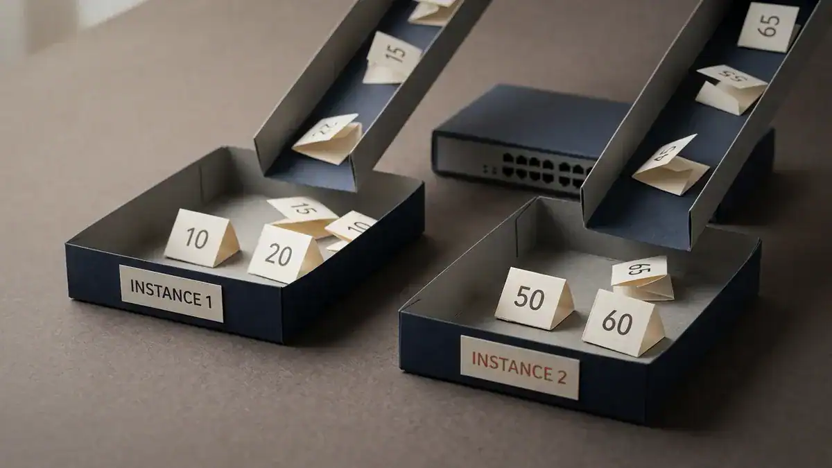
You decide which VLAN lands in which tray. The switch only ever runs one tree per tray.
Here’s the part worth getting right, because plenty of pages still get it wrong. MST started life as IEEE 802.1s in 2002, a standalone amendment. It hasn’t been standalone for a long time.
The contents were folded into 802.1Q, and the current base document is IEEE 802.1Q-2022. So when an article tells you “MST is defined in 802.1s,” that was true two decades ago. The protocol didn’t change. The paperwork moved.
And it’s still being worked on. IEEE 802.1Qdy-2025 was published on 2025-02-26, adding YANG modules for MSTP configuration and status reporting, driven largely by industrial automation networks. A protocol from 2002 getting a fresh amendment in 2025 tells you something about how much gear still runs it.
Studying for the CCNA? Reading an MST config and typing one into a switch that then splits into two regions are very different experiences. See what’s inside the CCNA Lab Workbook →
When Should You Use the Multiple Spanning Tree Protocol?
This is the question every other article skips, so here’s a straight answer.
Run MST when you have a lot of VLANs and a small number of genuinely different forwarding paths. Run Rapid PVST+ when you have few VLANs, or when you need per-VLAN control that can’t be grouped. Run neither in a modern data centre fabric, where VXLAN with EVPN handles this at Layer 3.
| Your situation | Run this | Why |
|---|---|---|
| Under about 50 VLANs, all Cisco | Rapid PVST+ | Simpler. The CPU cost isn’t hurting you yet |
| 100+ VLANs, campus or branch | MST | Flat CPU cost. Two or three instances cover it |
| Mixed vendors on the same Layer 2 | MST | It’s the IEEE standard. PVST+ is Cisco-only |
| You need two uplinks both carrying traffic | MST | Different root per instance splits the load |
| Every VLAN needs its own distinct path | Rapid PVST+ | Grouping would defeat the point |
| Spine and leaf data centre | Neither | VXLAN with EVPN. Every link forwards |
| Small office, one or two switches | Rapid PVST+ | MST is overhead you don’t need |
The honest version: most campus networks have two or three real traffic patterns and fifty VLAN numbers. MST exists because those two facts don’t have to match.

Same switch, same VLANs. The difference is how many trees it has to think about.
Vendor mix is the other big trigger. Rapid PVST+ is a Cisco extension. Put an Aruba, Juniper or Arista switch on the same Layer 2 domain and MST is the language they all speak. If you’re weighing the VLAN count that pushed you here in the first place, our note on VLAN vs subnet covers where those numbers usually come from.
Where does it stop making sense? Two places. Under 50 VLANs, and you’re solving a problem you don’t have. In a leaf-spine fabric, and spanning tree isn’t the loop prevention mechanism anymore.
How MST Works: Regions, Instances and the CIST
Three concepts. Get these and the config writes itself.
The MST region
A region is a group of switches that agree on the same VLAN-to-instance map. Switches only share a region when three things match exactly:
- Region name, up to 32 bytes, and it’s case sensitive
- Revision number, 0 to 65535
- The VLAN-to-instance mapping table, all 4,096 entries
All three. Every switch. Byte for byte. A single character out of place and the switch is in its own region of one, which is the failure we’ll come back to later.
Switches don’t compare the whole 4,096-entry table across the wire. They hash it into a digest and compare that, which is why a mismatch gives you no helpful error message. Two hashes differ. That’s all it knows.
The IST, instance 0
Instance 0 is the IST, the Internal Spanning Tree. It’s created automatically, you can’t delete it, and by default every VLAN on the switch lives in it until you map it somewhere else.
The IST is the only instance that talks to the outside world. It’s an RSTP instance that extends the Common Spanning Tree into your region, and it’s what carries BPDUs across the region boundary. Everything outside sees your entire region as one big virtual bridge.
MSTIs, instances 1 and up
Every instance you create yourself is an MSTI, a Multiple Spanning Tree Instance. These are RSTP instances that exist only inside the region. They never send BPDUs outside it, and the world beyond your boundary has no idea they exist.
Cisco supports up to 65 MST instances per region. You will almost certainly use two or three.
The CIST and the boundary
The CIST, Common and Internal Spanning Tree, is the tree that stitches your region to everything else. At a boundary port, the region replicates the IST BPDU across all VLANs to look like a PVST+ neighbour. That’s how an MST region and a Rapid PVST+ switch can sit next to each other without either falling over.
Useful mental model: think of your MST region as a single large switch in the eyes of the outside network. What happens inside it stays inside it.

The switch outside has no idea there are three switches in there. It sees the box.
When you map VLANs into instances, you’re working on top of VLANs and 802.1Q trunking, so the trunk config has to be right before any of this matters.
How to Configure Multiple Spanning Tree Protocol on Cisco Switches
Five steps. Commands are Cisco IOS and IOS-XE, verified against the current Catalyst configuration guides.
Step 1: Plan the VLAN-to-instance map first
Do this on paper before you touch a switch. Seriously.
Say you have VLANs 10 through 40 for one building and 50 through 80 for another, and two uplinks you’d like to both carry traffic. That’s two instances:
| Instance | VLANs | Root | Purpose |
|---|---|---|---|
| 0 (IST) | everything unmapped | SW1 | Boundary and leftovers |
| 1 | 10-40 | SW1 | Building A traffic, uplink 1 |
| 2 | 50-80 | SW2 | Building B traffic, uplink 2 |
Write it down. Every switch in the region needs this identical map, and “identical” is doing a lot of work in that sentence.
Step 2: Switch to MST mode
SW1(config)# spanning-tree mode mstDo this in a maintenance window. The switch tears down the running spanning tree and rebuilds it, and ports go through a transition while that happens.
Step 3: Build the region, then check show pending
SW1(config)# spanning-tree mst configuration
SW1(config-mst)# name SMENODE-CAMPUS
SW1(config-mst)# revision 1
SW1(config-mst)# instance 1 vlan 10-40
SW1(config-mst)# instance 2 vlan 50-80
SW1(config-mst)# show pending
That show pending is the most useful command in MST and almost nobody mentions it. Everything you type inside the MST submode is staged, not applied. It only goes live when you type exit. So show pending shows you what’s about to happen, and show current shows what’s running right now.
Got it wrong? Type abort instead of exit and nothing you typed ever happened.
SW1(config-mst)# exitNow repeat on every switch in the region. Same name, same revision, same instance map. Copy and paste it. Don’t retype it.
Step 4: Set a different root per instance
This is the whole payoff. Two instances, two roots, two uplinks carrying traffic.
On SW1:
SW1(config)# spanning-tree mst 0 root primary
SW1(config)# spanning-tree mst 1 root primary
SW1(config)# spanning-tree mst 2 root secondary
On SW2:
SW2(config)# spanning-tree mst 2 root primary
SW2(config)# spanning-tree mst 1 root secondary
Instance 1 now converges on SW1, instance 2 on SW2. Traffic for VLANs 10 to 40 takes one uplink, traffic for 50 to 80 takes the other, and each backs the other up. The root bridge election works exactly as it does in classic STP, just once per instance instead of once per VLAN.
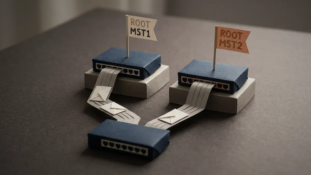
Two roots, two live uplinks. Under one tree, one of these ribbons would be sitting blocked.
Prefer setting priority by hand? It moves in steps of 4096:
SW1(config)# spanning-tree mst 1 priority 24576You can tune per-port cost and priority per instance too, from interface config mode:
SW1(config-if)# spanning-tree mst 1 cost 20000
SW1(config-if)# spanning-tree mst 1 port-priority 64
Port priority moves in steps of 16, default 128.
Step 5: Verify
SW1# show spanning-tree mst configuration
SW1# show spanning-tree mst
SW1# show spanning-tree mst 1
SW1# show spanning-tree mst interface GigabitEthernet1/0/1
Start with show spanning-tree mst configuration. If the name, revision and instance map on that output don’t match on every switch, stop and fix that before looking at anything else.
That one command is the whole spanning tree MST verification story. Everything else is detail.
Default MST Timers, and Why You Should Leave Them Alone
Worth knowing, mostly so you can recognise when someone has changed them.
| Setting | Default |
|---|---|
| Device priority | 32768 |
| Port priority | 128 |
| Hello time | 2 seconds |
| Forward-delay time | 15 seconds |
| Maximum-aging time | 20 seconds |
| Maximum hop count | 20 hops |
| Revision number | 0 |
| Region name | not set |
MST uses a hop count inside the region rather than max-age, defaulting to 20. Each switch decrements it. Once it hits zero the BPDU is discarded, which caps how far a region can stretch.
Leave the timers at default. The number of outages caused by somebody tuning hello time down to “speed up convergence” is not small, and RSTP’s handshake already handles fast failover without timer games.
That default revision number of 0 matters more than it looks. We’ll get to why.
How to Read show spanning-tree mst Output
Here’s a trimmed SW1 output with the parts that matter:
SW1# show spanning-tree mst

##### MST0    vlans mapped:   1-9,41-49,81-4094
Bridge        address 0023.04ee.be01  priority  24576 (24576 sysid 0)
Root          this switch for the CIST
Operational   hello time 2, forward delay 15, max age 20, txholdcount 6
Configured    hello time 2, forward delay 15, max age 20, max hops 20

Interface        Role Sts Cost      Prio.Nbr Type
---------------- ---- --- --------- -------- ----
Gi1/0/1          Desg FWD 20000     128.1    P2p
Gi1/0/2          Desg FWD 20000     128.2    P2p

##### MST1    vlans mapped:   10-40
Bridge        address 0023.04ee.be01  priority  24577 (24576 sysid 1)
Root          this switch for MST1

##### MST2    vlans mapped:   50-80
Bridge        address 0023.04ee.be01  priority  32770 (32768 sysid 2)
Root          address 0023.04ee.cd02  priority  24578 (24576 sysid 2)
              port    Gi1/0/2         cost 20000     rem hops 19
Four things to read off this:
vlans mappedon each instance header. Compare it against your plan. If MST0 is holding VLANs you meant to map elsewhere, your instance config didn’t take.priority 24577 (24576 sysid 1). That’s not a typo and nothing is broken. Cisco adds the instance number to the configured priority, same extended system ID trick used per VLAN in PVST+. 24576 + 1 = 24577.Root this switchversus aRoot addresspointing elsewhere. On MST2 above, SW1 is not the root, and it reaches the root out Gi1/0/2. That’s the load balancing working.rem hops 19. The hop count, counting down from 20. If you ever see this getting low, your region is stretched further than it should be.
Why Your MST Region Split in Two
This is the failure mode. If MST breaks on you, it’s probably this, and the symptom is confusing because nothing logs an error.
Here’s the failure that costs an afternoon. MST goes out across eleven switches. Ten come from a pasted config block. The eleventh gets added weeks later by someone who types the region name by hand and writes SMENODE-Campus instead of SMENODE-CAMPUS. One letter, wrong case.
The switch came up. No errors. No syslog message. Spanning tree converged. But that switch was now a region of one, its uplinks became boundary ports, and every VLAN behind it started following the CIST topology instead of the instance map. Traffic that should have taken the second uplink all piled onto the first. Nobody noticed until a Monday morning when the building ran at half its expected throughput.
Finding it took two hours. Confirming it took one command.

One letter in the wrong case, and that switch is a region of one. Nothing logs an error.
The diagnosis, in order:
SW11# show spanning-tree mst configurationRun it on the suspect switch and on a known-good neighbour. Compare three lines: name, revision, and the instance-to-VLAN map. They match or they don’t.
The usual culprits:
- Case. The region name is case sensitive.
CampusandCAMPUSare different regions. - Revision left at 0. Somebody set the name and mapped VLANs but forgot
revision. Default 0 against your 1, different region. - A VLAN mapped on some switches and not others. Even one VLAN in a different instance changes the digest.
- A trailing space in the name. Rare, ugly, and real.
- Forgetting
exit. Config staged in the submode never applied.show currentwill be empty while you swear the config is right.
The tell that you’re in this situation at all: run show spanning-tree mst and look at whether ports you expect to be internal are showing as boundary. A region that’s split shows boundary ports where there shouldn’t be any.
Want to break it on purpose and watch what happens? That’s the fastest way to learn this, and it’s exactly how the labs are built. The CCNA Lab Workbook ships 75 hands-on labs with the EVE-NG ISO, Packet Tracer files and verified solutions, mapped to the 200-301 blueprint.
Migrating from Rapid PVST+ to MST Without an Outage
Nobody covers this, and it’s where real deployments go wrong.
The move is disruptive by nature. spanning-tree mode mst rebuilds the tree from scratch on that switch, so ports transition and traffic pauses. Plan it as a change, not as a quick fix.
The order that hurts least:
- Build the full VLAN-to-instance map first, on paper, for every switch. Don’t improvise it switch by switch.
- Start at the distribution or core layer, not the access layer. Convert the switches that will hold your roots first, so the region grows outward from a stable centre.
- Configure the region on a switch before flipping it to MST mode where your platform allows it. The MST submode config is accepted in other modes and sits there staged.
- Convert neighbours in adjacent pairs, not scattered around the topology. Every conversion boundary is a PVST simulation boundary, and fewer of those at once means fewer surprises.
- Verify after each pair with
show spanning-tree mst configurationbefore moving on. Catching a mismatch across two switches takes a minute. Catching it across eleven takes an afternoon. - Run
clear spanning-tree detected-protocolson ports that came from a legacy neighbour and are stuck in a compatibility mode they no longer need.
One more thing. During the migration you’ll have MST switches next to Rapid PVST+ switches, and that works because of PVST simulation at the boundary. It works. It isn’t where you want to live permanently, because the boundary collapses all your per-VLAN granularity down to the IST topology.
Build an MST Lab in EVE-NG
Reading the config isn’t the same as watching instance 2 pick the other uplink. Three switches, twenty minutes.
The topology: three switches in a triangle, all links as 802.1Q trunks. VLANs 10, 20, 30 and 40 on the switches.
The build:
- Put all three in the same region. Name
LAB, revision 1,instance 1 vlan 10,20andinstance 2 vlan 30,40. - Make SW1 root for instance 1, SW2 root for instance 2.
- Run
show spanning-tree mston all three and find the blocked port for each instance. They should be different ports. That’s the point. - Now break it. Change the revision number on SW3 to 2. Run
show spanning-tree mstagain and watch SW3 become its own region. - Fix it. Watch it heal.
Step 4 is the one that teaches you something. Everyone can follow a config. Recognising a split region in the wild is the skill that’s actually worth having.
Need the environment? Install EVE-NG first, and check how much RAM you need before you start, because three IOSvL2 nodes want more than people expect. For a wider set to practise on, we’ve got free CCNA labs you can build in EVE-NG and a set of exam-focused topologies including the STP root bridge lab that this one builds on.
Running Packet Tracer instead? MST support there is limited and version dependent. Check your version before planning an evening around it.
MSTP in Networking vs BACnet MS/TP
Quick disambiguation, because the acronym is overloaded and search results mix them together.
MSTP in networking is the multiple spanning tree protocol, IEEE 802.1s, running on Ethernet switches at Layer 2.
BACnet MS/TP is Master-Slave/Token-Passing, a serial protocol running over RS-485 in building automation systems, HVAC controllers and the like. Completely unrelated. Different layer, different physical medium, different industry.
If you landed here looking for the building automation one, this isn’t it. If you’re a network engineer who searched “MSTP” and got HVAC results, now you know why.
Multiple Spanning Tree Protocol FAQ
MSTP vs RSTP: which is better?
Neither, and they’re not really competitors. RSTP (802.1w) is the fast convergence mechanism, and MST uses RSTP inside every one of its instances.
How do I configure MSTP?
Four commands and a plan. spanning-tree mode mst to switch modes, then spanning-tree mst configuration to enter the submode, then name, revision and instance N vlan X-Y to define the region, then exit to apply it. Set roots per instance with spanning-tree mst N root primary. Verify with show spanning-tree mst configuration on every switch and confirm all three region attributes match.
What is an MST region?
A group of switches sharing an identical region name, revision number and VLAN-to-instance mapping table. All three have to match exactly on every switch, including letter case. Switches compare a hash of the mapping table rather than the table itself, so a mismatch produces no useful error, just a switch quietly sitting in its own region.
What’s the difference between the IST and an MSTI?
The IST is instance 0. It’s created automatically, holds every unmapped VLAN, and it’s the only instance that exchanges BPDUs outside the region. MSTIs are instances 1 and up, created by you, and they never leave the region. Outside switches only ever see the IST.
How many MST instances can I use?
Cisco Catalyst platforms support up to 65 MST instances per region. In practice two or three is normal. The whole point is fewer trees, so creating a dozen instances works against the reason you chose MST.
Do all switches need the same VLAN-to-instance map?
Yes, on every switch you want in the same region. Miss one VLAN on one switch and that switch forms a separate region, its links become boundary ports, and your load balancing silently stops working. Paste the config block. Don’t retype it.
Is MST on the CCNA exam?
Spanning tree is on the blueprint and MST shows up as a concept rather than a deep configuration task at CCNA level. You should be able to say what an instance is, what a region requires, and why you’d group VLANs. Switching and Network Access grows to 25% of the blueprint in CCNA v2.0, which goes live on 2027-02-03, so spanning tree coverage is expanding rather than shrink
Bottom Line
Five things worth keeping:
- Multiple spanning tree protocol maps groups of VLANs onto shared instances, so your CPU cost stays flat whether you run 50 VLANs or 2,000.
- Use it above roughly 100 VLANs, or any time you have mixed vendors on the same Layer 2. Below 50 VLANs and all Cisco, Rapid PVST+ is simpler and fine.
- Region name, revision number and VLAN map must match exactly on every switch. Case sensitive, no error message when they don’t. This is the failure you’ll actually hit.
show pendingbeforeexit. Config in the MST submode is staged, not live.abortthrows it away if you got it wrong.- Two instances with two different roots is the entire payoff. Both uplinks carry traffic, and each is the other’s backup.
Build the triangle. Set two roots, confirm the blocked ports differ per instance, then break the revision number on one switch and watch the region split. That last step is worth more than the first three.
Ready to make the labs count? The CCNA Lab Workbook gives you 75 hands-on labs with the EVE-NG ISO, Packet Tracer files and verified solutions, mapped to the 200-301 blueprint. Want an instructor and a fixed schedule instead? Our sister site runs a live CCNA course at SMEnode Academy where you build these topologies alongside a room of other candidates.
Sources: Cisco: Understand the Multiple Spanning Tree Protocol (802.1s) · Cisco: Configuring Multiple Spanning-Tree Protocol, Catalyst 9600 IOS XE 17.16 · IEEE 802.1Qdy-2025, YANG for the Multiple Spanning Tree Protocol